Tuesday, 2 August 2011
Sunday, 31 July 2011
Friday, 29 July 2011
Friday, 1 April 2011
VPN Provider
vpnmaster company real vpn service Provider very good service, server quality useful reliable I am very happy with their service.
vpnmaster company real vpn service Provider very good service, server quality useful reliable I am very happy with their service.
Tuesday, 29 March 2011
Sonic Producer
The online programs are really good because they allow you to make your beats while keeping them saved online, which makes it easy for you to collaborate with others and also makes it easy for you to Here's the best software and site which you can use to make beats Just visit
The online programs are really good because they allow you to make your beats while keeping them saved online, which makes it easy for you to collaborate with others and also makes it easy for you to Here's the best software and site which you can use to make beats Just visit
Friday, 25 March 2011
cosmetic dentistry
keyword
A sign identical with a trademark is used in relation to goods or services’ within the meaning of these provisions when it has been selected as a keyword
keyword
A sign identical with a trademark is used in relation to goods or services’ within the meaning of these provisions when it has been selected as a keyword
www.casinopoker365.com
the Poker is very rally good
Will the poker craze last on the internet and in real time. Not being able to play for cash on the internet has turned a lot of people off to the game
the Poker is very rally good
Will the poker craze last on the internet and in real time. Not being able to play for cash on the internet has turned a lot of people off to the game
Thursday, 24 March 2011
Friday, 28 January 2011
How To configure Mikrotik DHCP Server
No doubt that providing static IP really inconvenient, especially a lot of PCs that will be set them IP. Because if there are same IP will also be conflict. Indeed there is a PC you should be given such a static IP just like a PC server and default gateway. Then another PC on the network just enough get automatic IP from the IP server called the DHCP server. DHCP is the Dynamic Host Configuration Protocol, service that will give automatic IP to the PC on the network imaginable. So the PC should not be turned off. If these pc is turned off then the other PC will lose the IP
On occasion this time, the following article will dwscribe how to make the DHCP server configuration through Winbox on Mikrotik PC Router. Here are step by step to setting up DHCP Server Pc Router.
1. Install MikrotikOs on your Pc router with two ethernet card ( 1 ethernet for internet connection (ether1) and 1 ethernet for Local connection (ether2)
2. Connect your pc router to Windows pc using utp cable, look at the picture below:
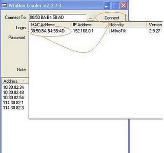
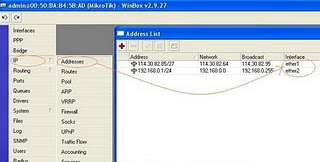
# Set your IP address....click Tab Menu IP------>Address---->Add
Ip for interface ether1 for example: 114.30.82.85/27
Ip for interface ether2 for example: 192.168.0.1/24
look at the picture below:
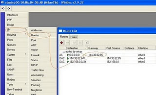
# Set Gateway for your internet connection on interface ether1 (internet connection)
IP--------Routes----Add
For Example Ip Gateway: 114.30.82.65
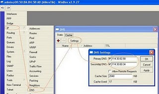
# Set your DNS Server...IP.....>DNS----tab Setting
For example DNS:
primary-dns: 114.30.82.90
secondary-dns: 114.30.80.34
# Setting DHCP Server
IP----Pool----Pools---->Add
Name: dhcppool
Addresses: 192.168.0.2-192.168.0.100
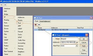
IP------DHCP Server----DHCP----Add
Name: dhcpserver
Interface: ether2
Address pool: dhcppool
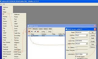
IP----->DHCP Server---DHCP---Networks---Add
Address: 192.168.0.0/24
Gateway: 192.168.0.1
DNS Server: 114.30.82.90
114.30.80.34
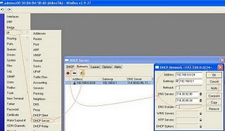
IP----Firewall-----Nat----Add
on tab General:Chain: src-nat
Out Interface: ether1
On tab Action: Action: masquerade
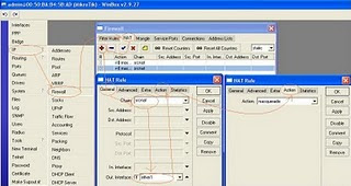
7. Done
Open Tab New Terminal to try your internet connection with Pc router DHCP Server

On occasion this time, the following article will dwscribe how to make the DHCP server configuration through Winbox on Mikrotik PC Router. Here are step by step to setting up DHCP Server Pc Router.
1. Install MikrotikOs on your Pc router with two ethernet card ( 1 ethernet for internet connection (ether1) and 1 ethernet for Local connection (ether2)
2. Connect your pc router to Windows pc using utp cable, look at the picture below:

# Set your IP address....click Tab Menu IP------>Address---->Add
Ip for interface ether1 for example: 114.30.82.85/27
Ip for interface ether2 for example: 192.168.0.1/24
look at the picture below:

# Set Gateway for your internet connection on interface ether1 (internet connection)
IP--------Routes----Add
For Example Ip Gateway: 114.30.82.65

# Set your DNS Server...IP.....>DNS----tab Setting
For example DNS:
primary-dns: 114.30.82.90
secondary-dns: 114.30.80.34

# Setting DHCP Server
IP----Pool----Pools---->Add
Name: dhcppool
Addresses: 192.168.0.2-192.168.0.100

IP------DHCP Server----DHCP----Add
Name: dhcpserver
Interface: ether2
Address pool: dhcppool

IP----->DHCP Server---DHCP---Networks---Add
Address: 192.168.0.0/24
Gateway: 192.168.0.1
DNS Server: 114.30.82.90
114.30.80.34

IP----Firewall-----Nat----Add
on tab General:Chain: src-nat
Out Interface: ether1
On tab Action: Action: masquerade

7. Done
Open Tab New Terminal to try your internet connection with Pc router DHCP Server

MikroTik RouterOS V2.4 DHCP Client and Server
MikroTik RouterOS V2.4 DHCP Client and Server
Document revision 12-Feb-2002
This document applies to the MikroTik RouterOS V2.5
Overview
DHCP (Dynamic Host Configuration Protocol) supports easy distribution of IP addresses for a network. The MikroTik RouterOS implementation includes both server and client modes and is compliant with RFC2131.
General usage of DHCP:
* For IP assignment in LAN (typically office networks)
* For IP assignment on cable-modem systems
* For IP assignment on wireless ISP systems
Installation
In V2.5, unlikely to the prior versions, the DHCP server and client are not included in the 'system' package. Please download the dhcp-2.x.npk package from the MikroTik's web site, upload the package to the router and reboot.
Use the /system package print command to see the list of installed packages.
Hardware Resource Usage
The DHCP server does not consume any significant resources. The DHCP client may consume high resource for five to ten seconds when acquiring an address or renewing an address.
DHCP Description
The DHCP protocol gives and allocates IP addresses to IP clients. DHCP is basically insecure and should only be used on secure networks. Port 67 is the DHCP listen port and port 68 is the DHPC transmit port.
DHCP Client Setup
The MikroTik RouterOS DHCP client may be attached to one Ethernet like interface. The client will accept an address, netmask, default gateway, and two dns server addresses. The IP address will be added to the interface with the netmask. The default gateway will be added to the routing table as a dynamic entry – when the DHCP client is disabled, the dynamic default route will be removed. If there is already a default route installed prior the DHCP client obtains one, the route obtained by the DHCP client would be shown as invalid.
The DNS-server from the DHCP server will be used as the router default DNS if the router DNS is set to 0.0.0.0 under the /ip dns settings.
To add a DHCP client to the router:
[MikroTik] ip dhcp-client> set enabled yes interface ether1 client-id test
Descriptions of arguments:
[MikroTik] - The text inside the brackets is the 'system identity' of the router. If the DHCP server requires a 'host name', then the MikroTik 'system identity' should be set to the same. This 'system identity' will be reported to the DHCP server as the 'host name'.
enabled - (yes / no). Enables or disables the DHCP client.
interface - Can be set to any Ethernet like interface – this includes wireless and EoIP tunnels.
client-id - (optional) If needed, it should correspond to the settings suggested by the network administrator or ISP.
To change the 'system identity', use the cammand:
[MikroTik]> system identity set name=Mikro2345
[Mikro2345]>
DHCP Server Setup
The router supports an individual server for each Ethernet like interface. The MikroTik RouterOS DHCP server supports the basic functions of giving each requesting client an IP address lease, default gateway, and DNS-server information.
To add a DHCP server:
[MikroTik] ip dhcp-server>
set ether1 enabled yes lease-time 72h from-address 10.5.0.1 \
to-address 10.5.0.100 netmask 255.255.255.0 gateway 10.5.0.254 \
dns-server 10.5.0.254 domain rm219
[MikroTik] ip dhcp-server> print
0 interface: ether1 enabled: yes from-address: 10.5.0.1
to-address: 10.5.0.100 lease-time: 3 days 0:00:00 netmask: 255.255.255.0
gateway: 10.5.0.254 src-address: 0.0.0.0 dns-server: 10.5.0.254
domain: ether1-area
1 interface: Local219 enabled: no from-address: 0.0.0.0 to-address: 0.0.0.0
lease-time: 0:10:00 netmask: 0.0.0.0 gateway: 0.0.0.0 src-address: 0.0.0.0
dns-server: 0.0.0.0 domain: ""
[MikroTik] ip dhcp-server>
Descriptions of arguments:
interface - All Ethernet like interfaces may run a DHCP server.
enabled - (yes / no) Enable or disable the DHCP server.
from-address - Beginning number of IP address range to give to requesting DHCP clients. This address must be in the range of a static address on the same interface.
to-address - Ending number of IP address range to give to requesting DHCP clients. This address must be in the range of a static address on the same interface.
lease-time - Dictates the time that a client may use an address. Suggested setting is three days 3d'. The client will request a new address' after this time limit expires.
netmask - The netmask to be given with the IP address coming from the range of addresses that can be given out.
gateway - The default gateway to be used by the DHCP client.
source-address - The address which the DHCP client must use to renew an IP address lease. If there is only one static address on the DHCP server interface and the source-address is left as 0.0.0.0, then the static address will be used. If there are multiple addresses on the interface, an address in the same subnet as the range of given addresses should be used.
dns-server - The DHCP client will use this as the default DNS server.
domain - The DHCP client will use this as the 'DNS domain' setting for the network adapter
Tuesday, 25 January 2011
Tuesday, 18 January 2011
Manual: RouterOS configuration with CD Intstall
CD Install Description
CD-Install allows to install MikroTik RouterOS to x86 boxes, which do not support Netinstall (all the RouterBOARDs should be reinstalled with Netinstall).
CD Install Requirements
Router
*
o x86 box with hard drive
o CD-ROM
Additional PC
*
o CD-ROM
o CD burning application
o MikroTik RouterOS CD installation ISO image
CD Install Example
Prepare MikroTik RouterOS CD Installation Disk
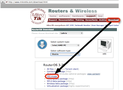
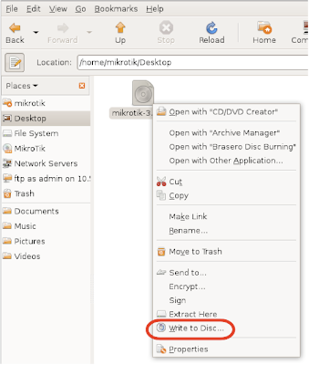
2. Burn ISO image to disk, you need PC with CD-ROM and application to write ISO files to CD. For Linux (the latest Ubuntu release) you can use built-in application. Mouse right-click on the .iso file and specify 'Write to Disk'. You got MikroTik RouterOS installation disk after process is finished.
Router Preconfiguration
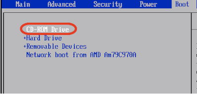
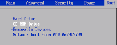
3. Switch on the x86 box, where you want to install MikroTik RouterOS, it should be with CD-ROM as well. Put MikroTik RouterOS installation disk to CD-ROM and set to boot from CD-ROM in BIOS settings,
4. x86 will boot from MikroTik RouterOS installation disk and should offer you to select the RouterOS Packages to install,
Package Selection
5. Select the packages you want to install, it is possible to select all packages with a or minimum with m, then Press i to install the RouterOS.
Installation
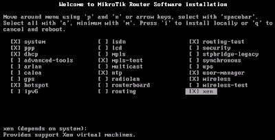
6. If you have previous installation of the RouterOS and want to reset the configuration, then answer no for the question 'Do you want to keep old configuration ?' and click y to proceed,
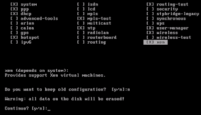
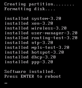
7. You will the process of the packages installation. Router will ask for the reboot after installation is finished,
8. MikroTik RouterOS is successfully installed, do not forget to eject CD installation disk and set PC to boot from Hard Drive,
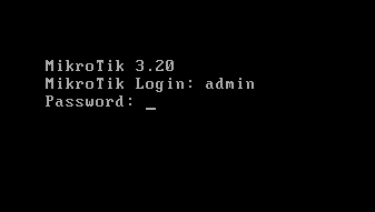
9. MikroTik RouterOS is booted and you are ready to login. Default login is admin without any password,
10. The last of the installation to license the router, use the software-id to purchase the license,
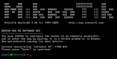
CD-Install allows to install MikroTik RouterOS to x86 boxes, which do not support Netinstall (all the RouterBOARDs should be reinstalled with Netinstall).
CD Install Requirements
Router
*
o x86 box with hard drive
o CD-ROM
Additional PC
*
o CD-ROM
o CD burning application
o MikroTik RouterOS CD installation ISO image
CD Install Example
Prepare MikroTik RouterOS CD Installation Disk

2. Burn ISO image to disk, you need PC with CD-ROM and application to write ISO files to CD. For Linux (the latest Ubuntu release) you can use built-in application. Mouse right-click on the .iso file and specify 'Write to Disk'. You got MikroTik RouterOS installation disk after process is finished.

Router Preconfiguration
3. Switch on the x86 box, where you want to install MikroTik RouterOS, it should be with CD-ROM as well. Put MikroTik RouterOS installation disk to CD-ROM and set to boot from CD-ROM in BIOS settings,

4. x86 will boot from MikroTik RouterOS installation disk and should offer you to select the RouterOS Packages to install,
Package Selection
5. Select the packages you want to install, it is possible to select all packages with a or minimum with m, then Press i to install the RouterOS.
Installation

6. If you have previous installation of the RouterOS and want to reset the configuration, then answer no for the question 'Do you want to keep old configuration ?' and click y to proceed,

7. You will the process of the packages installation. Router will ask for the reboot after installation is finished,
8. MikroTik RouterOS is successfully installed, do not forget to eject CD installation disk and set PC to boot from Hard Drive,

9. MikroTik RouterOS is booted and you are ready to login. Default login is admin without any password,

10. The last of the installation to license the router, use the software-id to purchase the license,


operating system

What is RouterOS?
MikroTik RouterOS is the operating system of MikroTik RouterBOARD hardware. It can also be installed on a PC and will turn it into a router with all the necessary features - routing, firewall, bandwidth management, wireless access point, backhaul link, hotspot gateway, VPN server and more.
RouterOS is a stand-alone operating system based on the Linux v2.6 kernel, and our goal here at MikroTik is to provide all these features with a quick and simple installation and an easy to use interface.
You can try RouterOS today, go to www.mikrotik.com and download the installation CD image. The free trial provides all of the features with no limitations. In the following pages you will find examples of some of the most important RouterOS features.
Configuration Reset Command
Command name: /system reset
Description
The command clears all configuration of the router and sets it to the default including the login name and password ('admin' and no password), IP addresses and other configuration is erased, interfaces will become disabled. After the reset command router will reboot.
Command Description
reset - erases router's configuration
Notes
If the router has been installed using netinstall and had a script specified as the initial configuration, the reset command executes this script after purging the configuration. To stop it doing so, you will have to reinstall the router.
Example
[admin@MikroTik] > system reset
Dangerous! Reset anyway? [y/N]: n
action cancelled
[admin@MikroTik] >
Configuration Management
General Information
Summary
This manual introduces you with commands which are used to perform the following functions:
* system backup
* system restore from a backup
* configuration export
* configuration import
* system configuration reset
Description
The configuration backup can be used for backing up MikroTik RouterOS configuration to a binary file, which can be stored on the router or downloaded from it using FTP. The configuration restore can be used for restoring the router's configuration from a backup file.
The configuration export can be used for dumping out MikroTik RouterOS configuration to the console screen or to a text (script) file, which can be downloaded from the router using FTP. The configuration import can be used to import the router configuration script from a text file.
System reset command is used to erase all configuration on the router. Before doing that, it might be useful to backup the router's configuration.
Note! In order to be sure that the backup will not fail, system backup load command must be used on the same computer with the same hardware where system backup save was done.
System Backup
Submenu level: /system backup
Description
The save command is used to store the entire router configuration in a backup file. The file is shown in the /file submenu. It can be downloaded via ftp to keep it as a backup for your configuration.
To restore the system configuration, for example, after a /system reset, it is possible to upload that file via ftp and load that backup file using load command in /system backup submenu.
Command Description
load name=[filename] - Load configuration backup from a file
save name=[filename] - Save configuration backup to a file
Example
To save the router configuration to file test:
[admin@MikroTik] system backup> save name=test
Configuration backup saved
[admin@MikroTik] system backup>
To see the files stored on the router:
[admin@MikroTik] > file print
# NAME TYPE SIZE CREATION-TIME
0 test.backup backup 12567 sep/08/2004 21:07:50
[admin@MikroTik] >
Example
To load the saved backup file test:
[admin@MikroTik] system backup> load name=test
Restore and reboot? [y/N]: y
...
The Export Command
Command name: /export
Description
The export command prints a script that can be used to restore configuration. The command can be invoked at any menu level, and it acts for that menu level and all menu levels below it. If the argument from is used, then it is possible to export only specified items. In this case export does not descend recursively through the command hierarchy. export also has the argument file, which allows you to save the script in a file on the router to retrieve it later via FTP.
Command Description
file=[filename] - saves the export to a file
from=[number] - specifies from which item to start to generate the export file
Example
[admin@MikroTik] > ip address print
Flags: X - disabled, I - invalid, D - dynamic
# ADDRESS NETWORK BROADCAST INTERFACE
0 10.1.0.172/24 10.1.0.0 10.1.0.255 bridge1
1 10.5.1.1/24 10.5.1.0 10.5.1.255 ether1
[admin@MikroTik] >
To make an export file:
[admin@MikroTik] ip address> export file=address
[admin@MikroTik] ip address>
To make an export file from only one item:
[admin@MikroTik] ip address> export file=address1 from=1
[admin@MikroTik] ip address>
To see the files stored on the router:
[admin@MikroTik] > file print
# NAME TYPE SIZE CREATION-TIME
0 address.rsc script 315 dec/23/2003 13:21:48
1 address1.rsc script 201 dec/23/2003 13:22:57
[admin@MikroTik] >
To export the setting on the display use the same command without the file argument:
[admin@MikroTik] ip address> export from=0,1
# nov/13/2004 13:25:30 by RouterOS 2.9
# software id = MGJ4-MAN
#
/ ip address
add address=10.1.0.172/24 network=10.1.0.0 broadcast=10.1.0.255 \
interface=bridge1 comment="" disabled=no
add address=10.5.1.1/24 network=10.5.1.0 broadcast=10.5.1.255 \
interface=ether1 comment="" disabled=no
[admin@MikroTik] ip address>
The Import Command
Command name: /import
Description
The root level command /import [file_name] restores the exported information from the specified file. This is used to restore configuration or part of it after a /system reset event or anything that causes configuration data loss.
Note that it is impossible to import the whole router configuration using this feature. It can only be used to import a part of configuration (for example, firewall rules) in order to spare you some typing.
Command Description
file=[filename] - loads the exported configuration from a file to router
Example
To load the saved export file use the following command:
[admin@MikroTik] > import address.rsc
Opening script file address.rsc
Script file loaded successfully
[admin@MikroTik] >
Configuration Reset
Command name: /system reset
Description
The command clears all configuration of the router and sets it to the default including the login name and password ('admin' and no password), IP addresses and other configuration is erased, interfaces will become disabled. After the reset command router will reboot.
Command Description
reset - erases router's configuration
Notes
If the router has been installed using netinstall and had a script specified as the initial configuration, the reset command executes this script after purging the configuration. To stop it doing so, you will have to reinstall the router.
Example
[admin@MikroTik] > system reset
Dangerous! Reset anyway? [y/N]: n
action cancelled
[admin@MikroTik] >
File Transfer Protocol Server
Submenu level : /file
Description
MikroTik RouterOS has an industry standard FTP server feature. It uses ports 20 and 21 for communication with other hosts on the network. Do not disable these ports on your router!
Uploaded files as well as exported configuration or backup files can be accessed under /file menu. There you can also delete unwanted files from your router.
Authorization via ftp uses router's system user account names and passwords.
Property Description
name (read-only: text) - item name
type (read-only: file | directory | unknown) - item type
package size (read-only: integer) - package size
creation-time (read-only: time) - item creation date and time
package-name (read-only: name) - package name
package-version (read-only: text) - package version
package-build-time (read-only: time) - build time of the package
Example
Suppose we need to upload a software package system-2.7rc4.npk to a router with IP address 192.168.0.2 using generic text mode FTP client from a Linux workstation (the procedure and commands are the same also for Windows workstations):
user@wildcat:~/work$ ftp 192.168.0.2
Connected to 192.168.0.2.
220 MikroTik FTP server (MikroTik v2.7rc3) ready
Name (192.168.0.2:root): admin
331 Password required for admin
Password:
230 User admin logged in
Remote system type is UNIX.
ftp> binary
200 Type set to I
ftp> send
(local-file) /home/psi/system-2.7rc4.npk
(remote-file) system-2.7rc4.npk
local: /home/psi/system-2.7rc4.npk remote: system-2.7rc4.npk
200 PORT command successful
150 Opening BINARY mode data connection for '/system-2.7rc4.npk'
226 Transfer complete
8391343 bytes sent in 12.61 secs (649.7 kB/s)
ftp> close
221 Closing
ftp> quit
user@wildcat:~/work$
Now you can see this package on the router:
[admin@MikroTik] file> print
# NAME TYPE SIZE CREATION-TIME
0 system-2.7rc4.npk package 8391343 apr/30/2003 17:09:55
1 hotspot directory mar/08/2003 16:14:19
[admin@MikroTik] file>
MikroTik RouterOS implements a File Transfer Protocol (FTP) server feature
Description
MikroTik RouterOS has an industry standard FTP server facility. It uses ports 20 and 21 for communication with other hosts on the network. Uploaded files as well as exported configuration or backup files can be accessed under /file menu. There you can delete unnecessary files from the router.
Authorization for FTP service uses router's system user account names and passwords. The ftp local user policy controls the access rights to the FTP server.
Property Description
* contents (text) - file contents (for text files only; size limit - 4kB)
* creation-time (read-only: time) - item creation date and time
* name (read-only: name) - item name
* package-architecture (read-only: [text]) - RouterOS software package target machine architecture (for package files only)
* package-build-time (read-only: [date]) - RouterOS software package build time (for package files only)
* package-name (read-only: [text]) - RouterOS software package name (for package files only)
* package-version (read-only: [text]) - RouterOS software package version number (for package files only)
* size (read-only: integer) - package size in bytes
* type (read-only: text) - item type. Few file types are recognized by extension: backup, directory, package, script, ssh key, but other files are just marked by their extension (.html file, for example)
Sunday, 16 January 2011
Basic Installation of RouterOS System
Installation
This example shows how to install and configure Mikrotik RoterOS.
First download new RouterOS form here [1]
Then write iso image file on CD, and put in cdrom and turn on.

Press "a" key for select all and then press "i"
Answer "n" to first question and "y" to second

installation remove cd from cdrom and press "Enter"
after rebooting type "admin" as login and no password.
Add IP
When mikrotik prompt is ready assign ip to NIC:
/ip address
add address=10.0.0.1 interface=ether1
add address=192.168.0.1 interface=ether2
ether1 = WAN ( Connected To Your Router ) Alone -- ether2= LAN ( Connected To Your Switch (hub) With Clients -- now add gateway ip:
/ip route
add gateway=10.0.0.0
10.0.0.1,192.168.0.1 and 10.0.0.0 is sample data and you should use your ip for setting
if use your ip now you can ping internet
ping 4.2.2.4
4.2.2.4 64 byte ping: ttl=242 time=255 ms
4.2.2.4 64 byte ping: ttl=242 time=243 ms
4.2.2.4 64 byte ping: ttl=242 time=247 ms
4.2.2.4 64 byte ping: ttl=242 time=243 ms
4 packets transmitted, 4 packets received, 0% packet loss
round-trip min/avg/max = 243/247.0/255 ms
ok.
NAT
nat will use until client with invalid ip connect to internet, so we must run nat on mikrotik and set client ip in range of 192.168.0.2 and set client gateway to 192.168.0.1(Secend NIC of mikrotik)
/ip firewall nat
add chain=srcnat action=masquerade out-interface=ether1
this will be route all traffic to interface 1 that have an valid ip so will be nat and go to internet
This example shows how to install and configure Mikrotik RoterOS.
First download new RouterOS form here [1]
Then write iso image file on CD, and put in cdrom and turn on.

Press "a" key for select all and then press "i"
Answer "n" to first question and "y" to second

installation remove cd from cdrom and press "Enter"
after rebooting type "admin" as login and no password.
Add IP
When mikrotik prompt is ready assign ip to NIC:
/ip address
add address=10.0.0.1 interface=ether1
add address=192.168.0.1 interface=ether2
ether1 = WAN ( Connected To Your Router ) Alone -- ether2= LAN ( Connected To Your Switch (hub) With Clients -- now add gateway ip:
/ip route
add gateway=10.0.0.0
10.0.0.1,192.168.0.1 and 10.0.0.0 is sample data and you should use your ip for setting
if use your ip now you can ping internet
ping 4.2.2.4
4.2.2.4 64 byte ping: ttl=242 time=255 ms
4.2.2.4 64 byte ping: ttl=242 time=243 ms
4.2.2.4 64 byte ping: ttl=242 time=247 ms
4.2.2.4 64 byte ping: ttl=242 time=243 ms
4 packets transmitted, 4 packets received, 0% packet loss
round-trip min/avg/max = 243/247.0/255 ms
ok.
NAT
nat will use until client with invalid ip connect to internet, so we must run nat on mikrotik and set client ip in range of 192.168.0.2 and set client gateway to 192.168.0.1(Secend NIC of mikrotik)
/ip firewall nat
add chain=srcnat action=masquerade out-interface=ether1
this will be route all traffic to interface 1 that have an valid ip so will be nat and go to internet
MikroTik RouterOS Basic Setup Guide
http://.mikrotik.com/documentation/manual_2.7/Basic/Basic.html
Description
# MikroTik RouterOS™ turns a standard PC computer into a powerful network router. Just add standard network PC interfaces to expand the router capabilities. Remote control with easy real-time Windows application (WinBox)
# Telnet/SSH/console/serial console control with RADIUS authentication
# Advanced bandwidth control
# Network firewall with packet-filtering, masquerading, network address translation, logging and connection monitoring
# DHCP support
# HotSpot gateway with RADIUS authentication
# Ethernet 10/100/1000Mb/s
# Wireless client and Access Point 2.4GHz 11Mb/s (IEEE802.11b), 5GHz 54Mb/s (IEEE802.11a) and 2.4GHz 54Mb/s (IEEE802.11g) with RADIUS authentication for AP
# V.35 synchronous 8.448Mb/s with Sync-PPP, HDLC or Frame Relay
# X.21 synchronous 8.448Mb/s with Sync-PPP, HDLC or Frame Relay
# Async PPP (up to 128 ports) with RADIUS authetication for modem pools
# E1/T1 support
# IP Telephony Gateway
# Built-in Web-proxy
# And much more
The Guide describes the basic steps of installing and configuring a dedicated PC router running MikroTik RouterOS™.
Setting up MikroTik RouterOS™
Downloading and Installing the MikroTik RouterOS™
The download and installation process of the MikroTik RouterOS™ is described in the following diagram:
1. Download the basic installation archive file.
Depending on the desired media to be used for installing the MikroTik RouterOS™ please chose one of the following archive types for downloading:
* ISO image of the installation CD, if you have a CD writer for creating CDs. The ISO image is in the MTcdimage_v2-7-x_dd-mmm-yyyy.zip archive file containing a bootable CD image. The CD will be used for booting up the dedicated PC and installing the MikroTik RouterOS™ on its hard-drive or flash-drive.
* MikroTik Disk Maker, if you want to create 3.5" installation floppies. The Disk Maker is a self-extracting archive DiskMaker_v2-7-x_dd-mmm-yyyy.exe file, which should be run on your Windows 95/98/NT4/2K/XP workstation to create the installation floppies. The installation floppies will be used for booting up the dedicated PC and installing the MikroTik RouterOS™ on its hard-drive or flash-drive.
* Netinstall, if you want to install RouterOS™ over a LAN with one floppy boot disk, or alternatively using PXE-boot option supported by some network interface cards, that allows truly networked installation. Netinstall program works on Windows 95/98/NT4/2K/XP.
2. Create the installation media
Use the appropriate installation archive to create the Installation CD or floppies.
* For the CD, write the ISO image onto a blank CD.
* For the floppies, run the Disk Maker on your Windows workstation to create the installation floppies. Follow the instructions and insert the floppies in your FDD as requested, label them as Disk 1,2,3, etc.
3. Install the MikroTik RouterOS™ software.
Your dedicated PC router hardware should have:
* An advanced 4th generation (core frequency 100MHz or more), 5th generation (Intel Pentium, Cyrix 6X86, AMD K5 or comparable) or newer Intel IA-32 (i386) compatible motherboard and processor (uniprocessor only, dual processors and other SMP configurations are not supported);
* from 32MB to 1GB RAM (from 48MB suggested);
* 30MB or more PRIMARY MASTER IDE HDD or IDE flashdrive.
* A network adapter (NE2000 compatible PCI or ISA Ethernet card, or any other supported NIC, see the supported device list on our web page);
For installation purposes (and only for that time) you should also have:
* A SECONDARY MASTER CD drive set as primary boot device, if you want to use the created CD for installing the MikroTik RouterOS™ onto the primary master HDD;
* A 3.5" FDD set as primary boot device, if you want to use the created set of floppies for installing the MikroTik RouterOS™;
* A monitor and keyboard for installation and initial setup of the MikroTik Router. The monitor and keyboard do not need to be connected to the router after it is set up for connecting to it over the network.
Boot up your dedicated PC router from the Installation Media you created and follow the instructions on the console screen while the HDD is reformatted and MikroTik RouterOS™ installed on it.
After successful installation please remove the installation media from your CD or floppy disk drive and hit 'Enter' to reboot the router. While the router will be starting up for the first time you will be given a Software ID for your installation and asked to supply a valid software license key (Software Key) for it. Write down the Software ID. You will need it to obtain the Software License through the MikroTik Account Server. If you need extra time to obtain the Software License Key, you may want to power off the router. Type shutdown in the Software key prompt and power the router off when the router is halted.
Notes
The installation from CD or network requires Base (paid) License. If you intend to obtain the Free Demo License, you should use the floppy installation media.
The hard disk will be entirely reformatted during the installation and all data on it will be lost!
You can move the hard drive with MikroTik RouterOS™ installed to a new hardware without loosing a license, but you cannot move the RouterOS™ to a different hard drive without purchasing an another license (except hardware failure situations). For additional information write to support[at]mikrotik.com
Obtaining the Software License
The MikroTik RouterOS™ Software licensing process is described in the following diagram:
After installing the router and starting it up for the first time you will be given a Software ID.
1. Write down the Software ID reported by the RouterOS™.
2. If you have an account with MikroTik, follow to the next step.
If you do not have an account at www.mikrotik.com, just press the 'New' button on the upper right-hand corner of the MikroTik's web page to create your account.
You will be presented with the Account Sign-Up Form where you chose your account name and fill in the required information.
3. To obtain the Software License Key, log on to your account at www.mikrotik.com entering your account name and password (upper right-hand corner on this webpage), for example:
4. After logging on to the Account Server select "Free Demo License" or "Order Software License" in the Account Menu.
5. The Software Key will be sent to the email address, which has been specified in your account setup.
6. Read your email and enter the Software Key at the router's console, for example:
Software ID: 5T4V-IUT
Software key: 4N7X-UZ8-6SP
Instead of entering the license key you can enter shutdown to shut down the router and enter the license key later, or enter display to read the License Agreement, or help to see a help message.
After entering the correct Software License Key you will be presented with the MikroTik Router's login prompt.
Notes
The CD or Netinstall installation cannot be 'unlocked' with the Free Demo Key. Use the Floppy installation or purchase a Licensed Key.
Logging into the MikroTik Router
When logging into the router via terminal console, you will be presented with the MikroTik RouterOS™ login prompt. Use 'admin' and no password (hit 'Enter') for logging on to the router for the first time, for example:
MikroTik v2.7
Login: admin
Password:
The password can be changed with the /password command.
Adding Software Packages
The basic installation comes with only the "system" package and few other packages. This includes basic IP routing and router administration. To have additional features such as IP Telephony, OSPF, wireless and so on, you will need to download additional software packages.
The additional software packages should have the same version as the system package. If not, the package won't be installed. Please consult the MikroTik RouterOS™ Software Package Installation and Upgrading Manual for more detailed information about installing additional software packages.
Software Licensing Issues
If you want to upgrade your 'free' version of MikroTik RouterOS™ installation to a 'paid' version, please purchase the new Software License KEY for the Software ID you used when getting the 'free' demo license. Similarly, if additional license is required to enable the functionality of a software package, the license should be obtained for the Software ID of your system. The new key should be entered using the /system license set key command, and the router should be rebooted afterwards:
[admin@MikroTik] ip firewall src-nat> /system license print
software-id: "SB6T-R8T"
key: "3YIV-ZW8-DH2"
upgradable-unitl: apr/01/2004
[admin@MikroTik] system license> feature print
Flags: X - disabled
# FEATURE
0 X AP
1 X synchronous
2 X radiolan
3 X wireless-2.4gHz
4 licensed
[admin@MikroTik] system license> set key=D46G-IJ6-QW3
[admin@MikroTik] system license>/system reboot
Reboot, yes? [y/N]: y
system will reboot shortly
Notes
If there is no appropriate license, the appropriate interfaces wont show up under the interface list, even though the packages can be installed on the MikroTik RouterOS™ and corresponding drivers loaded.
Navigating the Terminal Console
Welcome Screen and Command Prompt
After logging into the router you will be presented with the MikroTik RouterOS™ Welcome Screen and command prompt, for example:
MMM MMM KKK TTTTTTTTTTT KKK
MMMM MMMM KKK TTTTTTTTTTT KKK
MMM MMMM MMM III KKK KKK RRRRRR OOOOOO TTT III KKK KKK
MMM MM MMM III KKKKK RRR RRR OOO OOO TTT III KKKKK
MMM MMM III KKK KKK RRRRRR OOO OOO TTT III KKK KKK
MMM MMM III KKK KKK RRR RRR OOOOOO TTT III KKK KKK
MikroTik RouterOS v2.7 (c) 1999-2003 http://www.mikrotik.com/
Terminal xterm detected, using multiline mode
[admin@MikroTik] >
The command prompt shows the identity name of the router and the current menu level, for example:
[admin@MikroTik] > Base level menu
[admin@MikroTik] interface> Interface configuration
[admin@MikroTik] ip address> IP Address management
Commands
The list of available commands at any menu level can be obtained by entering the question mark '?', for example:
[admin@MikroTik] > ?
driver Driver management
file Local router file storage.
import Run exported configuration script
interface Interface configuration
log System logs
password Change password
ping Send ICMP Echo packets
port Serial ports
quit Quit console
radius Radius client settings
redo Redo previosly undone action
setup Do basic setup of system
snmp SNMP settings
undo Undo previous action
user User management
ppp Point to Point Protocol
ip IP options
queue Bandwidth management
system System information and utilities
tool Diagnostics tools
routing Various routing protocol settings
export Print or save an export script that can be used to restore
configuration
[admin@MikroTik] > ip ?
accounting Traffic accounting
address Address management
arp ARP entries management
dns DNS settings
firewall Firewall management
neighbor Neighbors
packing Packet packing settings
pool IP address pools
route Route management
service IP services
policy-routing Policy routing
upnp
dhcp-client DHCP client settings
dhcp-server DHCP server settings
dns-cache DNS cache management
ipsec IP security
export Print or save an export script that can be used to restore
configuration
[admin@MikroTik] > ip
The list of available commands and menus has short descriptions next to the items. You can move to the desired menu level by typing its name and hitting the [Enter] key, for example:
[admin@MikroTik] > Base level menu
[admin@MikroTik] > driver Enter 'driver' to move to the driver level
menu
[admin@MikroTik] driver> / Enter '/' to move to the base level menu
from any level
[admin@MikroTik] > interface Enter 'interface' to move to the interface
level menu
[admin@MikroTik] interface> /ip Enter '/ip' to move to the IP level menu
from any level
[admin@MikroTik] ip>
A command or an argument does not need to be completed, if it is not ambiguous. For example, instead of typing 'interface' you can type just 'in' or 'int'. To complete a command use the [Tab] key.
The commands may be invoked from the menu level, where they are located, by typing its name. If the command is in a different menu level than the current one, then the command should be invoked using its full (absolute) or relative path, for example:
[admin@MikroTik] ip route> print Prints the routing table
[admin@MikroTik] ip route> .. address print Prints the IP address table
[admin@MikroTik] ip route> /ip address print Prints the IP address table
The commands may have arguments. The arguments have their names and values. Some commands, may have a required argument that has no name.
Summary on executing the commands and moving between the menu levels
Command Action
command [Enter] Execute the command
[?] Show the list of all available commands
command [?] Display help on the command and the list of arguments
command argument [?] Display help on the command's argument
[Tab] Complete the command/word. If the input is ambiguous, a
second [Tab] gives possible options
/ Move up to the base level
/command Execute the base level command
.. Move up one level
"" Enter an empty string
"word1 word2" Enter 2 words that contain a space
You can abbreviate names of levels, commands and arguments.
For the IP address configuration, instead of using the 'address' and 'netmask' arguments, in most cases you can specify the address together with the number of true bits in the network mask, i.e., there is no need to specify the 'netmask' separately. Thus, the following two entries would be equivalent:
/ip address add address 10.0.0.1/24 interface ether1
/ip address add address 10.0.0.1 netmask 255.255.255.0 interface ether1
Notes
You must specify the size of the network mask in the address argument, even if it is the 32-bit subnet, i.e., use 10.0.0.1/32 for address 10.0.0.1 and netmask 255.255.255.255
Accessing the Router Remotely Using Web Browser and WinBox Console
Summary
The MikroTik router can also be accessed remotely using http and WinBox Console, for example, using the web browser of your workstation.
Description
The Winbox Console is used for accessing the MikroTik Router configuration and management features using graphical user interface.
All Winbox interface functions are as close as possible to Console functions: all Winbox functions are exactly in the same place in Terminal Console and vice versa (except functions that are not implemented in Winbox). That is why there are no Winbox sections in the manual.
The Winbox Console plugin loader, the winbox.exe program, can be retrieved from the MikroTik router, the URL is http://router_address/winbox/winbox.exe Use any web browser on Windows 95/98/ME/NT4.0/2000/XP to retrieve the router's web page with the mentioned link.
Note that if you change the default port for www service on the router, you will have to specify it just after the IP address separated by column (eg. 10.0.0.1:8080).
The winbox plugins are cached on the local disk for each MikroTik RouterOS™ version. The plugins are not downloaded, if they are in the cache, and the router has not been upgraded since the last time it has been accessed.
Starting the Winbox Console
When connecting to the MikroTik router via http (TCP port 80 by default), the router's Welcome Page is displayed in the web browser, for example:
By clicking on the Winbox Console link you can start the winbox.exe download. Choose the option "Run this program from its current location" and click "OK":
Accept the security warning, if any:
Alternatively, you can save the winbox.exe program to your disk and run it from there.
The winbox.exe program opens the Winbox login window. Login to the router by specifying the IP address (and the port number if you have changed it from the default value of 80), user name, and password, for example:
Watch the download process of Winbox plugins:
The Winbox console is opened after the plugins have been downloaded:
The Winbox Console uses TCP port 3986 (not secure) or 3987 (secure; requires security package to be installed). After logging on to the router you can work with the MikroTik router's configuration through the Winbox console and perform the same tasks as using the regular console.
Overview of Common Functions
You can use the menu bar to navigate through the router's configuration menus, open configuration windows. By double clicking on some list items in the windows you can open configuration windows for the specific items, and so on.
There are some hints for using the Winbox Console:
* To open the required window, simply click on the corresponding menu item.
* To add a new entry you should click on the icon in the corresponding window.
* To remove an existing entry click on the icon.
* To enable an item, click on the icon.
* To disable an item, click on the icon.
* To make or edit a comment for a selected item, click on the icon.
* To refresh a window, click on the icon.
* To undo an action, click on the icon above the main menu.
* To redo an action, click on the icon above the main menu.
* To logout from the Winbox Console, click on the icon.
Troubleshooting for Winbox Console
* I cannot open the Winbox Console
o Check the port and address for www service in /ip service print list. Make sure the address you are connecting from matches the network you've specified in address field and that you've specified the correct port in the Winbox loader. The command /ip service set www port=80 address=0.0.0.0/0 will change these values to the default ones so you will be able to connect specifying just the correct address of the router in the address field of Winbox loader
o The Winbox Console uses TCP port 3986 (not secure) or 3987 (secure; requires security package to be installed). Make sure you have access to it through the firewall.
Configuring Basic Functions
Working with Interfaces
Before configuring the IP addresses and routes please check the /interface menu to see the list of available interfaces. If you have Plug-and-Play cards installed in the router, it is most likely that the device drivers have been loaded for them automatically, and the relevant interfaces appear on the /interface print list, for example:
[admin@MikroTik] interface> print
Flags: X - disabled, D - dynamic, R - running
# NAME TYPE MTU
0 R ether1 ether 1500
1 R ether2 ether 1500
2 R ether3 ether 1500
3 R ether4 ether 1500
4 R ether5 ether 1500
5 R sync1 sync 1500
6 R pc1 pc 1500
7 R ether6 ether 1500
8 R prism1 prism 1500
[admin@MikroTik] interface>
The interfaces need to be enabled, if you want to use them for communications. Use the /interface enable name command to enable the interface with a given name or number, for example:
[admin@MikroTik] interface> print
Flags: X - disabled, D - dynamic, R - running
# NAME TYPE MTU
0 X ether1 ether 1500
0 X ether2 ether 1500
[admin@MikroTik] interface> enable 0
[admin@MikroTik] interface> enable ether2
[admin@MikroTik] interface> print
Flags: X - disabled, D - dynamic, R - running
# NAME MTU TYPE
0 R ether1 ether 1500
0 R ether2 ether 1500
[admin@MikroTik] interface>
The interface name can be changed to a more descriptive one by using the /interface set command:
[admin@MikroTik] interface> set 0 name=Public
[admin@MikroTik] interface> set 1 name=Local
[admin@MikroTik] interface> print
Flags: X - disabled, D - dynamic, R - running
# NAME MTU TYPE
0 R Public ether 1500
0 R Local ether 1500
[admin@MikroTik] interface>
Use of the 'setup' Command
The initial setup of the router can be done by using the /setup command which enables an interface, assigns an address/netmask to it, and configures the default route. If you do not use the setup command, or need to modify/add the settings for addresses and routes, please follow the steps described below.
Notes
The device drivers for NE2000 compatible ISA cards need to be loaded using the add command under the /drivers menu. For example, to load the driver for a card with IO address 0x280 and IRQ 5, it is enough to issue the command:
[admin@MikroTik] driver> add name=ne2k-isa io=0x280
[admin@MikroTik] driver> print
Flags: I - invalid, D - dynamic
# DRIVER IRQ IO MEMORY ISDN-PROTOCOL
0 D RealTek 8139
1 D Intel EtherExpressPro
2 D PCI NE2000
3 ISA NE2000 280
4 Moxa C101 Synchronous C8000
[admin@MikroTik] driver>
There are some other drivers that should be added manually. Please refer to the respective manual sections for the detailed information on how drivers are to be loaded.
Adding Addresses
Assume you need to configure the MikroTik router for the following network setup:
In the current example we use two networks:
* The local LAN with network address 192.168.0.0 and 24-bit netmask 255.255.255.0 The router's address is 192.168.0.254 in this network.
* The ISP's network with address 10.0.0.0 and 24-bit netmask 255.255.255.0 The router's address is 10.0.0.217 in this network.
The addresses can be added and viewed using the following commands:
[admin@MikroTik] ip address> add address 10.0.0.217/24 interface Public
[admin@MikroTik] ip address> add address 192.168.0.254/24 interface Local
[admin@MikroTik] ip address> print
Flags: X - disabled, I - invalid, D - dynamic
# ADDRESS NETWORK BROADCAST INTERFACE
0 10.0.0.217/24 10.0.0.217 10.0.0.255 Public
1 192.168.0.254/24 192.168.0.0 192.168.0.255 Local
[admin@MikroTik] ip address>
Here, the network mask has been specified in the value of the address argument. Alternatively, the argument 'netmask' could have been used with the value '255.255.255.0'. The network and broadcast addresses were not specified in the input since they could be calculated automatically.
Notes
Please note that the addresses assigned to different interfaces of the router should belong to different networks.
Configuring the Default Route
You can see two dynamic (D) and connected (C) routes, which have been added automatically when the addresses were added in the example above:
[admin@MikroTik] ip route> print
Flags: X - disabled, I - invalid, D - dynamic, J - rejected,
C - connect, S - static, R - rip, O - ospf, B - bgp
# DST-ADDRESS G GATEWAY DISTANCE INTERFACE
0 DC 192.168.0.0/24 r 0.0.0.0 0 Local
1 DC 10.0.0.0/24 r 0.0.0.0 0 Public
[admin@MikroTik] ip route> print detail
Flags: X - disabled, I - invalid, D - dynamic, J - rejected,
C - connect, S - static, R - rip, O - ospf, B - bgp
0 DC dst-address=192.168.0.0/24 preferred-source=192.168.0.254
gateway=0.0.0.0 gateway-state=reachable distance=0 interface=Local
1 DC dst-address=10.0.0.0/24 preferred-source=10.0.0.217 gateway=0.0.0.0
gateway-state=reachable distance=0 interface=Public
[admin@MikroTik] ip route>
These routes show, that IP packets with destination to 10.0.0.0/24 would be sent through the interface Public, whereas IP packets with destination to 192.168.0.0/24 would be sent through the interface Local. However, you need to specify where the router should forward packets, which have destination other than networks connected directly to the router.
Example
In the following example the default route (destination 0.0.0.0, netmask 0.0.0.0) will be added. In this case it is the ISP's gateway 10.0.0.1, which can be reached through the interface Public:
[admin@MikroTik] ip route> add gateway=10.0.0.1
[admin@MikroTik] ip route> print
Flags: X - disabled, I - invalid, D - dynamic, J - rejected,
C - connect, S - static, R - rip, O - ospf, B - bgp
# DST-ADDRESS G GATEWAY DISTANCE INTERFACE
0 S 0.0.0.0/0 r 10.0.0.1 1 Public
1 DC 192.168.0.0/24 r 0.0.0.0 0 Local
2 DC 10.0.0.0/24 r 0.0.0.0 0 Public
[admin@MikroTik] ip route>
Here, the default route is listed under #0. As we see, the gateway 10.0.0.1 can be reached through the interface 'Public'. If the gateway was specified incorrectly, the value for the argument 'interface' would be unknown.
Notes
You cannot add two routes to the same destination, i.e., destination-address/netmask! It applies to the default routes as well. Instead, you can enter multiple gateways for one destination. For more information on IP routes, please read the relevant topic in the Manual.
If you have added an unwanted static route accidentally, use the remove command to delete the unneeded one. You will not be able to delete dynamic (DC) routes. They are added automatically and represent routes to the networks the router connected directly.
Testing the Network Connectivity
From now on, the /ping command can be used to test the network connectivity on both interfaces. You can reach any host on both connected networks from the router.
Example
In the example below it's seen, hows does ping command work:
[admin@MikroTik] ip route> /ping 10.0.0.4
10.0.0.4 64 byte ping: ttl=255 time=7 ms
10.0.0.4 64 byte ping: ttl=255 time=5 ms
10.0.0.4 64 byte ping: ttl=255 time=5 ms
3 packets transmitted, 3 packets received, 0% packet loss
round-trip min/avg/max = 5/5.6/7 ms
[admin@MikroTik] ip route>
[admin@MikroTik] ip route> /ping 192.168.0.1
192.168.0.1 64 byte ping: ttl=255 time=1 ms
192.168.0.1 64 byte ping: ttl=255 time=1 ms
192.168.0.1 64 byte ping: ttl=255 time=1 ms
3 packets transmitted, 3 packets received, 0% packet loss
round-trip min/avg/max = 1/1.0/1 ms
[admin@MikroTik] ip route>
The workstation and the laptop can reach (ping) the router at its local address 192.168.0.254, If the router's address 192.168.0.254 is specified as the default gateway in the TCP/IP configuration of both the workstation and the laptop, then you should be able to ping the router:
C:\>ping 192.168.0.254
Reply from 192.168.0.254: bytes=32 time=10ms TTL=253
Reply from 192.168.0.254: bytes=32 time<10ms TTL=253
Reply from 192.168.0.254: bytes=32 time<10ms TTL=253
C:\>ping 10.0.0.217
Reply from 10.0.0.217: bytes=32 time=10ms TTL=253
Reply from 10.0.0.217: bytes=32 time<10ms TTL=253
Reply from 10.0.0.217: bytes=32 time<10ms TTL=253
C:\>ping 10.0.0.4
Request timed out.
Request timed out.
Request timed out.
C:\>
Notes
You cannot access anything beyond the router (network 10.0.0.0/24 and the Internet), unless you do the one of the following:
* Use source network address translation (masquerading) on the MikroTik router to 'hide' your private LAN 192.168.0.0/24 (see the information below), or
* Add a static route on the ISP's gateway 10.0.0.1, which specifies the host 10.0.0.217 as the gateway to network 192.168.0.0/24. Then all hosts on the ISP's network, including the server, will be able to communicate with the hosts on the LAN.
To set up routing, it is required that you have some knowledge of configuring TCP/IP networks. There is a comprehensive list of IP resources compiled by Uri Raz at http://www.private.org.il/tcpip_rl.html We strongly recommend that you obtain more knowledge, if you have difficulties configuring your network setups.
Application Examples
Next will be discussed situation with 'hiding' the private LAN 192.168.0.0/24 'behind' one address 10.0.0.217 given to you by the ISP.
Application Example with Masquerading
If you want to 'hide' the private LAN 192.168.0.0/24 'behind' one address 10.0.0.217 given to you by the ISP, you should use the source network address translation (masquerading) feature of the MikroTik router. Masquerading is useful, if you want to access the ISP's network and the Internet appearing as all requests coming from the host 10.0.0.217 of the ISP's network. The masquerading will change the source IP address and port of the packets originated from the network 192.168.0.0/24 to the address 10.0.0.217 of the router when the packet is routed through it.
Masquerading conserves the number of global IP addresses required and it lets the whole network use a single IP address in its communication with the world.
To use masquerading, a source NAT rule with action 'masquerade' should be added to the firewall configuration:
[admin@MikroTik] ip firewall src-nat> add action=masquerade out-interface=Public
[admin@MikroTik] ip firewall src-nat> print
Flags: X - disabled, I - invalid, D - dynamic
0 src-address=0.0.0.0/0:0-65535 dst-address=0.0.0.0/0:0-65535
out-interface=Public protocol=all icmp-options=any:any flow=""
connection="" content="" limit-count=0 limit-burst=0 limit-time=0s
action=masquerade to-src-address=0.0.0.0 to-src-port=0-65535
[admin@MikroTik] ip firewall src-nat>
Notes
Please consult the Firewall Manual for more information on masquerading.
Application Example with Bandwidth Management
Mikrotik RouterOS™ V2.7 offers extensive queue management.
Assume you want to limit the bandwidth to 128kbps on downloads and 64kbps on uploads for all hosts on the LAN. Bandwidth limitation is done by applying queues for outgoing interfaces regarding the traffic flow. It is enough to add two queues at the MikroTik router:
[admin@MikroTik] queue simple> add interface=Local max-limit=128000
[admin@MikroTik] queue simple> add interface=Public max-limit=64000
[admin@MikroTik] queue simple> print
Flags: X - disabled, I - invalid, D - dynamic
0 name="queue1" src-address=0.0.0.0/0 dst-address=0.0.0.0/0
interface=Local limit-at=0 queue=default priority=8 max-limit=128000
1 name="queue2" src-address=0.0.0.0/0 dst-address=0.0.0.0/0
interface=Public limit-at=0 queue=default priority=8 max-limit=64000
[admin@MikroTik] queue simple>
Leave all other parameters as set by default. The limit is approximately 128kbps going to the LAN (download) and 64kbps leaving the client's LAN (upload).
Notes
The queues have been added for the outgoing interfaces regarding the traffic flow.
Please consult the Queues Manual for more information on bandwidth management and queuing.
Application Example with NAT
Assume we have moved the server in our previous examples from the public network to our local one:
The server'would have been s address now is 192.168.0.4, and we are running web server on it that listens to the TCP port 80. We want to make it accessible from the Internet at address:port 10.0.0.217:80. This can be done by means of Static Network Address translation (NAT) at the MikroTik Router. The Public address:port 10.0.0.217:80 will be translated to the Local address:port 192.168.0.4:80. One destination NAT rule is required for translating the destination address and port:
[admin@MikroTik] ip firewall dst-nat> add action=nat protocol=tcp \
dst-address=10.0.0.217/32:80 to-dst-address=192.168.0.4
[admin@MikroTik] ip firewall dst-nat> print
Flags: X - disabled, I - invalid, D - dynamic
0 src-address=0.0.0.0/0:0-65535 in-interface=all
dst-address=10.1.0.217/32:80 protocol=tcp icmp-options=any:any flow=""
src-mac-address=00:00:00:00:00:00 limit-count=0 limit-burst=0
limit-time=0s action=nat to-dst-address=192.168.0.4 to-dst-port=0-65535
[admin@MikroTik] ip firewall dst-nat>
Notes
Please consult the Firewall Manual for more information on NAT
Description
# MikroTik RouterOS™ turns a standard PC computer into a powerful network router. Just add standard network PC interfaces to expand the router capabilities. Remote control with easy real-time Windows application (WinBox)
# Telnet/SSH/console/serial console control with RADIUS authentication
# Advanced bandwidth control
# Network firewall with packet-filtering, masquerading, network address translation, logging and connection monitoring
# DHCP support
# HotSpot gateway with RADIUS authentication
# Ethernet 10/100/1000Mb/s
# Wireless client and Access Point 2.4GHz 11Mb/s (IEEE802.11b), 5GHz 54Mb/s (IEEE802.11a) and 2.4GHz 54Mb/s (IEEE802.11g) with RADIUS authentication for AP
# V.35 synchronous 8.448Mb/s with Sync-PPP, HDLC or Frame Relay
# X.21 synchronous 8.448Mb/s with Sync-PPP, HDLC or Frame Relay
# Async PPP (up to 128 ports) with RADIUS authetication for modem pools
# E1/T1 support
# IP Telephony Gateway
# Built-in Web-proxy
# And much more
The Guide describes the basic steps of installing and configuring a dedicated PC router running MikroTik RouterOS™.
Setting up MikroTik RouterOS™
Downloading and Installing the MikroTik RouterOS™
The download and installation process of the MikroTik RouterOS™ is described in the following diagram:
1. Download the basic installation archive file.
Depending on the desired media to be used for installing the MikroTik RouterOS™ please chose one of the following archive types for downloading:
* ISO image of the installation CD, if you have a CD writer for creating CDs. The ISO image is in the MTcdimage_v2-7-x_dd-mmm-yyyy.zip archive file containing a bootable CD image. The CD will be used for booting up the dedicated PC and installing the MikroTik RouterOS™ on its hard-drive or flash-drive.
* MikroTik Disk Maker, if you want to create 3.5" installation floppies. The Disk Maker is a self-extracting archive DiskMaker_v2-7-x_dd-mmm-yyyy.exe file, which should be run on your Windows 95/98/NT4/2K/XP workstation to create the installation floppies. The installation floppies will be used for booting up the dedicated PC and installing the MikroTik RouterOS™ on its hard-drive or flash-drive.
* Netinstall, if you want to install RouterOS™ over a LAN with one floppy boot disk, or alternatively using PXE-boot option supported by some network interface cards, that allows truly networked installation. Netinstall program works on Windows 95/98/NT4/2K/XP.
2. Create the installation media
Use the appropriate installation archive to create the Installation CD or floppies.
* For the CD, write the ISO image onto a blank CD.
* For the floppies, run the Disk Maker on your Windows workstation to create the installation floppies. Follow the instructions and insert the floppies in your FDD as requested, label them as Disk 1,2,3, etc.
3. Install the MikroTik RouterOS™ software.
Your dedicated PC router hardware should have:
* An advanced 4th generation (core frequency 100MHz or more), 5th generation (Intel Pentium, Cyrix 6X86, AMD K5 or comparable) or newer Intel IA-32 (i386) compatible motherboard and processor (uniprocessor only, dual processors and other SMP configurations are not supported);
* from 32MB to 1GB RAM (from 48MB suggested);
* 30MB or more PRIMARY MASTER IDE HDD or IDE flashdrive.
* A network adapter (NE2000 compatible PCI or ISA Ethernet card, or any other supported NIC, see the supported device list on our web page);
For installation purposes (and only for that time) you should also have:
* A SECONDARY MASTER CD drive set as primary boot device, if you want to use the created CD for installing the MikroTik RouterOS™ onto the primary master HDD;
* A 3.5" FDD set as primary boot device, if you want to use the created set of floppies for installing the MikroTik RouterOS™;
* A monitor and keyboard for installation and initial setup of the MikroTik Router. The monitor and keyboard do not need to be connected to the router after it is set up for connecting to it over the network.
Boot up your dedicated PC router from the Installation Media you created and follow the instructions on the console screen while the HDD is reformatted and MikroTik RouterOS™ installed on it.
After successful installation please remove the installation media from your CD or floppy disk drive and hit 'Enter' to reboot the router. While the router will be starting up for the first time you will be given a Software ID for your installation and asked to supply a valid software license key (Software Key) for it. Write down the Software ID. You will need it to obtain the Software License through the MikroTik Account Server. If you need extra time to obtain the Software License Key, you may want to power off the router. Type shutdown in the Software key prompt and power the router off when the router is halted.
Notes
The installation from CD or network requires Base (paid) License. If you intend to obtain the Free Demo License, you should use the floppy installation media.
The hard disk will be entirely reformatted during the installation and all data on it will be lost!
You can move the hard drive with MikroTik RouterOS™ installed to a new hardware without loosing a license, but you cannot move the RouterOS™ to a different hard drive without purchasing an another license (except hardware failure situations). For additional information write to support[at]mikrotik.com
Obtaining the Software License
The MikroTik RouterOS™ Software licensing process is described in the following diagram:
After installing the router and starting it up for the first time you will be given a Software ID.
1. Write down the Software ID reported by the RouterOS™.
2. If you have an account with MikroTik, follow to the next step.
If you do not have an account at www.mikrotik.com, just press the 'New' button on the upper right-hand corner of the MikroTik's web page to create your account.
You will be presented with the Account Sign-Up Form where you chose your account name and fill in the required information.
3. To obtain the Software License Key, log on to your account at www.mikrotik.com entering your account name and password (upper right-hand corner on this webpage), for example:
4. After logging on to the Account Server select "Free Demo License" or "Order Software License" in the Account Menu.
5. The Software Key will be sent to the email address, which has been specified in your account setup.
6. Read your email and enter the Software Key at the router's console, for example:
Software ID: 5T4V-IUT
Software key: 4N7X-UZ8-6SP
Instead of entering the license key you can enter shutdown to shut down the router and enter the license key later, or enter display to read the License Agreement, or help to see a help message.
After entering the correct Software License Key you will be presented with the MikroTik Router's login prompt.
Notes
The CD or Netinstall installation cannot be 'unlocked' with the Free Demo Key. Use the Floppy installation or purchase a Licensed Key.
Logging into the MikroTik Router
When logging into the router via terminal console, you will be presented with the MikroTik RouterOS™ login prompt. Use 'admin' and no password (hit 'Enter') for logging on to the router for the first time, for example:
MikroTik v2.7
Login: admin
Password:
The password can be changed with the /password command.
Adding Software Packages
The basic installation comes with only the "system" package and few other packages. This includes basic IP routing and router administration. To have additional features such as IP Telephony, OSPF, wireless and so on, you will need to download additional software packages.
The additional software packages should have the same version as the system package. If not, the package won't be installed. Please consult the MikroTik RouterOS™ Software Package Installation and Upgrading Manual for more detailed information about installing additional software packages.
Software Licensing Issues
If you want to upgrade your 'free' version of MikroTik RouterOS™ installation to a 'paid' version, please purchase the new Software License KEY for the Software ID you used when getting the 'free' demo license. Similarly, if additional license is required to enable the functionality of a software package, the license should be obtained for the Software ID of your system. The new key should be entered using the /system license set key command, and the router should be rebooted afterwards:
[admin@MikroTik] ip firewall src-nat> /system license print
software-id: "SB6T-R8T"
key: "3YIV-ZW8-DH2"
upgradable-unitl: apr/01/2004
[admin@MikroTik] system license> feature print
Flags: X - disabled
# FEATURE
0 X AP
1 X synchronous
2 X radiolan
3 X wireless-2.4gHz
4 licensed
[admin@MikroTik] system license> set key=D46G-IJ6-QW3
[admin@MikroTik] system license>/system reboot
Reboot, yes? [y/N]: y
system will reboot shortly
Notes
If there is no appropriate license, the appropriate interfaces wont show up under the interface list, even though the packages can be installed on the MikroTik RouterOS™ and corresponding drivers loaded.
Navigating the Terminal Console
Welcome Screen and Command Prompt
After logging into the router you will be presented with the MikroTik RouterOS™ Welcome Screen and command prompt, for example:
MMM MMM KKK TTTTTTTTTTT KKK
MMMM MMMM KKK TTTTTTTTTTT KKK
MMM MMMM MMM III KKK KKK RRRRRR OOOOOO TTT III KKK KKK
MMM MM MMM III KKKKK RRR RRR OOO OOO TTT III KKKKK
MMM MMM III KKK KKK RRRRRR OOO OOO TTT III KKK KKK
MMM MMM III KKK KKK RRR RRR OOOOOO TTT III KKK KKK
MikroTik RouterOS v2.7 (c) 1999-2003 http://www.mikrotik.com/
Terminal xterm detected, using multiline mode
[admin@MikroTik] >
The command prompt shows the identity name of the router and the current menu level, for example:
[admin@MikroTik] > Base level menu
[admin@MikroTik] interface> Interface configuration
[admin@MikroTik] ip address> IP Address management
Commands
The list of available commands at any menu level can be obtained by entering the question mark '?', for example:
[admin@MikroTik] > ?
driver Driver management
file Local router file storage.
import Run exported configuration script
interface Interface configuration
log System logs
password Change password
ping Send ICMP Echo packets
port Serial ports
quit Quit console
radius Radius client settings
redo Redo previosly undone action
setup Do basic setup of system
snmp SNMP settings
undo Undo previous action
user User management
ppp Point to Point Protocol
ip IP options
queue Bandwidth management
system System information and utilities
tool Diagnostics tools
routing Various routing protocol settings
export Print or save an export script that can be used to restore
configuration
[admin@MikroTik] > ip ?
accounting Traffic accounting
address Address management
arp ARP entries management
dns DNS settings
firewall Firewall management
neighbor Neighbors
packing Packet packing settings
pool IP address pools
route Route management
service IP services
policy-routing Policy routing
upnp
dhcp-client DHCP client settings
dhcp-server DHCP server settings
dns-cache DNS cache management
ipsec IP security
export Print or save an export script that can be used to restore
configuration
[admin@MikroTik] > ip
The list of available commands and menus has short descriptions next to the items. You can move to the desired menu level by typing its name and hitting the [Enter] key, for example:
[admin@MikroTik] > Base level menu
[admin@MikroTik] > driver Enter 'driver' to move to the driver level
menu
[admin@MikroTik] driver> / Enter '/' to move to the base level menu
from any level
[admin@MikroTik] > interface Enter 'interface' to move to the interface
level menu
[admin@MikroTik] interface> /ip Enter '/ip' to move to the IP level menu
from any level
[admin@MikroTik] ip>
A command or an argument does not need to be completed, if it is not ambiguous. For example, instead of typing 'interface' you can type just 'in' or 'int'. To complete a command use the [Tab] key.
The commands may be invoked from the menu level, where they are located, by typing its name. If the command is in a different menu level than the current one, then the command should be invoked using its full (absolute) or relative path, for example:
[admin@MikroTik] ip route> print Prints the routing table
[admin@MikroTik] ip route> .. address print Prints the IP address table
[admin@MikroTik] ip route> /ip address print Prints the IP address table
The commands may have arguments. The arguments have their names and values. Some commands, may have a required argument that has no name.
Summary on executing the commands and moving between the menu levels
Command Action
command [Enter] Execute the command
[?] Show the list of all available commands
command [?] Display help on the command and the list of arguments
command argument [?] Display help on the command's argument
[Tab] Complete the command/word. If the input is ambiguous, a
second [Tab] gives possible options
/ Move up to the base level
/command Execute the base level command
.. Move up one level
"" Enter an empty string
"word1 word2" Enter 2 words that contain a space
You can abbreviate names of levels, commands and arguments.
For the IP address configuration, instead of using the 'address' and 'netmask' arguments, in most cases you can specify the address together with the number of true bits in the network mask, i.e., there is no need to specify the 'netmask' separately. Thus, the following two entries would be equivalent:
/ip address add address 10.0.0.1/24 interface ether1
/ip address add address 10.0.0.1 netmask 255.255.255.0 interface ether1
Notes
You must specify the size of the network mask in the address argument, even if it is the 32-bit subnet, i.e., use 10.0.0.1/32 for address 10.0.0.1 and netmask 255.255.255.255
Accessing the Router Remotely Using Web Browser and WinBox Console
Summary
The MikroTik router can also be accessed remotely using http and WinBox Console, for example, using the web browser of your workstation.
Description
The Winbox Console is used for accessing the MikroTik Router configuration and management features using graphical user interface.
All Winbox interface functions are as close as possible to Console functions: all Winbox functions are exactly in the same place in Terminal Console and vice versa (except functions that are not implemented in Winbox). That is why there are no Winbox sections in the manual.
The Winbox Console plugin loader, the winbox.exe program, can be retrieved from the MikroTik router, the URL is http://router_address/winbox/winbox.exe Use any web browser on Windows 95/98/ME/NT4.0/2000/XP to retrieve the router's web page with the mentioned link.
Note that if you change the default port for www service on the router, you will have to specify it just after the IP address separated by column (eg. 10.0.0.1:8080).
The winbox plugins are cached on the local disk for each MikroTik RouterOS™ version. The plugins are not downloaded, if they are in the cache, and the router has not been upgraded since the last time it has been accessed.
Starting the Winbox Console
When connecting to the MikroTik router via http (TCP port 80 by default), the router's Welcome Page is displayed in the web browser, for example:
By clicking on the Winbox Console link you can start the winbox.exe download. Choose the option "Run this program from its current location" and click "OK":
Accept the security warning, if any:
Alternatively, you can save the winbox.exe program to your disk and run it from there.
The winbox.exe program opens the Winbox login window. Login to the router by specifying the IP address (and the port number if you have changed it from the default value of 80), user name, and password, for example:
Watch the download process of Winbox plugins:
The Winbox console is opened after the plugins have been downloaded:
The Winbox Console uses TCP port 3986 (not secure) or 3987 (secure; requires security package to be installed). After logging on to the router you can work with the MikroTik router's configuration through the Winbox console and perform the same tasks as using the regular console.
Overview of Common Functions
You can use the menu bar to navigate through the router's configuration menus, open configuration windows. By double clicking on some list items in the windows you can open configuration windows for the specific items, and so on.
There are some hints for using the Winbox Console:
* To open the required window, simply click on the corresponding menu item.
* To add a new entry you should click on the icon in the corresponding window.
* To remove an existing entry click on the icon.
* To enable an item, click on the icon.
* To disable an item, click on the icon.
* To make or edit a comment for a selected item, click on the icon.
* To refresh a window, click on the icon.
* To undo an action, click on the icon above the main menu.
* To redo an action, click on the icon above the main menu.
* To logout from the Winbox Console, click on the icon.
Troubleshooting for Winbox Console
* I cannot open the Winbox Console
o Check the port and address for www service in /ip service print list. Make sure the address you are connecting from matches the network you've specified in address field and that you've specified the correct port in the Winbox loader. The command /ip service set www port=80 address=0.0.0.0/0 will change these values to the default ones so you will be able to connect specifying just the correct address of the router in the address field of Winbox loader
o The Winbox Console uses TCP port 3986 (not secure) or 3987 (secure; requires security package to be installed). Make sure you have access to it through the firewall.
Configuring Basic Functions
Working with Interfaces
Before configuring the IP addresses and routes please check the /interface menu to see the list of available interfaces. If you have Plug-and-Play cards installed in the router, it is most likely that the device drivers have been loaded for them automatically, and the relevant interfaces appear on the /interface print list, for example:
[admin@MikroTik] interface> print
Flags: X - disabled, D - dynamic, R - running
# NAME TYPE MTU
0 R ether1 ether 1500
1 R ether2 ether 1500
2 R ether3 ether 1500
3 R ether4 ether 1500
4 R ether5 ether 1500
5 R sync1 sync 1500
6 R pc1 pc 1500
7 R ether6 ether 1500
8 R prism1 prism 1500
[admin@MikroTik] interface>
The interfaces need to be enabled, if you want to use them for communications. Use the /interface enable name command to enable the interface with a given name or number, for example:
[admin@MikroTik] interface> print
Flags: X - disabled, D - dynamic, R - running
# NAME TYPE MTU
0 X ether1 ether 1500
0 X ether2 ether 1500
[admin@MikroTik] interface> enable 0
[admin@MikroTik] interface> enable ether2
[admin@MikroTik] interface> print
Flags: X - disabled, D - dynamic, R - running
# NAME MTU TYPE
0 R ether1 ether 1500
0 R ether2 ether 1500
[admin@MikroTik] interface>
The interface name can be changed to a more descriptive one by using the /interface set command:
[admin@MikroTik] interface> set 0 name=Public
[admin@MikroTik] interface> set 1 name=Local
[admin@MikroTik] interface> print
Flags: X - disabled, D - dynamic, R - running
# NAME MTU TYPE
0 R Public ether 1500
0 R Local ether 1500
[admin@MikroTik] interface>
Use of the 'setup' Command
The initial setup of the router can be done by using the /setup command which enables an interface, assigns an address/netmask to it, and configures the default route. If you do not use the setup command, or need to modify/add the settings for addresses and routes, please follow the steps described below.
Notes
The device drivers for NE2000 compatible ISA cards need to be loaded using the add command under the /drivers menu. For example, to load the driver for a card with IO address 0x280 and IRQ 5, it is enough to issue the command:
[admin@MikroTik] driver> add name=ne2k-isa io=0x280
[admin@MikroTik] driver> print
Flags: I - invalid, D - dynamic
# DRIVER IRQ IO MEMORY ISDN-PROTOCOL
0 D RealTek 8139
1 D Intel EtherExpressPro
2 D PCI NE2000
3 ISA NE2000 280
4 Moxa C101 Synchronous C8000
[admin@MikroTik] driver>
There are some other drivers that should be added manually. Please refer to the respective manual sections for the detailed information on how drivers are to be loaded.
Adding Addresses
Assume you need to configure the MikroTik router for the following network setup:
In the current example we use two networks:
* The local LAN with network address 192.168.0.0 and 24-bit netmask 255.255.255.0 The router's address is 192.168.0.254 in this network.
* The ISP's network with address 10.0.0.0 and 24-bit netmask 255.255.255.0 The router's address is 10.0.0.217 in this network.
The addresses can be added and viewed using the following commands:
[admin@MikroTik] ip address> add address 10.0.0.217/24 interface Public
[admin@MikroTik] ip address> add address 192.168.0.254/24 interface Local
[admin@MikroTik] ip address> print
Flags: X - disabled, I - invalid, D - dynamic
# ADDRESS NETWORK BROADCAST INTERFACE
0 10.0.0.217/24 10.0.0.217 10.0.0.255 Public
1 192.168.0.254/24 192.168.0.0 192.168.0.255 Local
[admin@MikroTik] ip address>
Here, the network mask has been specified in the value of the address argument. Alternatively, the argument 'netmask' could have been used with the value '255.255.255.0'. The network and broadcast addresses were not specified in the input since they could be calculated automatically.
Notes
Please note that the addresses assigned to different interfaces of the router should belong to different networks.
Configuring the Default Route
You can see two dynamic (D) and connected (C) routes, which have been added automatically when the addresses were added in the example above:
[admin@MikroTik] ip route> print
Flags: X - disabled, I - invalid, D - dynamic, J - rejected,
C - connect, S - static, R - rip, O - ospf, B - bgp
# DST-ADDRESS G GATEWAY DISTANCE INTERFACE
0 DC 192.168.0.0/24 r 0.0.0.0 0 Local
1 DC 10.0.0.0/24 r 0.0.0.0 0 Public
[admin@MikroTik] ip route> print detail
Flags: X - disabled, I - invalid, D - dynamic, J - rejected,
C - connect, S - static, R - rip, O - ospf, B - bgp
0 DC dst-address=192.168.0.0/24 preferred-source=192.168.0.254
gateway=0.0.0.0 gateway-state=reachable distance=0 interface=Local
1 DC dst-address=10.0.0.0/24 preferred-source=10.0.0.217 gateway=0.0.0.0
gateway-state=reachable distance=0 interface=Public
[admin@MikroTik] ip route>
These routes show, that IP packets with destination to 10.0.0.0/24 would be sent through the interface Public, whereas IP packets with destination to 192.168.0.0/24 would be sent through the interface Local. However, you need to specify where the router should forward packets, which have destination other than networks connected directly to the router.
Example
In the following example the default route (destination 0.0.0.0, netmask 0.0.0.0) will be added. In this case it is the ISP's gateway 10.0.0.1, which can be reached through the interface Public:
[admin@MikroTik] ip route> add gateway=10.0.0.1
[admin@MikroTik] ip route> print
Flags: X - disabled, I - invalid, D - dynamic, J - rejected,
C - connect, S - static, R - rip, O - ospf, B - bgp
# DST-ADDRESS G GATEWAY DISTANCE INTERFACE
0 S 0.0.0.0/0 r 10.0.0.1 1 Public
1 DC 192.168.0.0/24 r 0.0.0.0 0 Local
2 DC 10.0.0.0/24 r 0.0.0.0 0 Public
[admin@MikroTik] ip route>
Here, the default route is listed under #0. As we see, the gateway 10.0.0.1 can be reached through the interface 'Public'. If the gateway was specified incorrectly, the value for the argument 'interface' would be unknown.
Notes
You cannot add two routes to the same destination, i.e., destination-address/netmask! It applies to the default routes as well. Instead, you can enter multiple gateways for one destination. For more information on IP routes, please read the relevant topic in the Manual.
If you have added an unwanted static route accidentally, use the remove command to delete the unneeded one. You will not be able to delete dynamic (DC) routes. They are added automatically and represent routes to the networks the router connected directly.
Testing the Network Connectivity
From now on, the /ping command can be used to test the network connectivity on both interfaces. You can reach any host on both connected networks from the router.
Example
In the example below it's seen, hows does ping command work:
[admin@MikroTik] ip route> /ping 10.0.0.4
10.0.0.4 64 byte ping: ttl=255 time=7 ms
10.0.0.4 64 byte ping: ttl=255 time=5 ms
10.0.0.4 64 byte ping: ttl=255 time=5 ms
3 packets transmitted, 3 packets received, 0% packet loss
round-trip min/avg/max = 5/5.6/7 ms
[admin@MikroTik] ip route>
[admin@MikroTik] ip route> /ping 192.168.0.1
192.168.0.1 64 byte ping: ttl=255 time=1 ms
192.168.0.1 64 byte ping: ttl=255 time=1 ms
192.168.0.1 64 byte ping: ttl=255 time=1 ms
3 packets transmitted, 3 packets received, 0% packet loss
round-trip min/avg/max = 1/1.0/1 ms
[admin@MikroTik] ip route>
The workstation and the laptop can reach (ping) the router at its local address 192.168.0.254, If the router's address 192.168.0.254 is specified as the default gateway in the TCP/IP configuration of both the workstation and the laptop, then you should be able to ping the router:
C:\>ping 192.168.0.254
Reply from 192.168.0.254: bytes=32 time=10ms TTL=253
Reply from 192.168.0.254: bytes=32 time<10ms TTL=253
Reply from 192.168.0.254: bytes=32 time<10ms TTL=253
C:\>ping 10.0.0.217
Reply from 10.0.0.217: bytes=32 time=10ms TTL=253
Reply from 10.0.0.217: bytes=32 time<10ms TTL=253
Reply from 10.0.0.217: bytes=32 time<10ms TTL=253
C:\>ping 10.0.0.4
Request timed out.
Request timed out.
Request timed out.
C:\>
Notes
You cannot access anything beyond the router (network 10.0.0.0/24 and the Internet), unless you do the one of the following:
* Use source network address translation (masquerading) on the MikroTik router to 'hide' your private LAN 192.168.0.0/24 (see the information below), or
* Add a static route on the ISP's gateway 10.0.0.1, which specifies the host 10.0.0.217 as the gateway to network 192.168.0.0/24. Then all hosts on the ISP's network, including the server, will be able to communicate with the hosts on the LAN.
To set up routing, it is required that you have some knowledge of configuring TCP/IP networks. There is a comprehensive list of IP resources compiled by Uri Raz at http://www.private.org.il/tcpip_rl.html We strongly recommend that you obtain more knowledge, if you have difficulties configuring your network setups.
Application Examples
Next will be discussed situation with 'hiding' the private LAN 192.168.0.0/24 'behind' one address 10.0.0.217 given to you by the ISP.
Application Example with Masquerading
If you want to 'hide' the private LAN 192.168.0.0/24 'behind' one address 10.0.0.217 given to you by the ISP, you should use the source network address translation (masquerading) feature of the MikroTik router. Masquerading is useful, if you want to access the ISP's network and the Internet appearing as all requests coming from the host 10.0.0.217 of the ISP's network. The masquerading will change the source IP address and port of the packets originated from the network 192.168.0.0/24 to the address 10.0.0.217 of the router when the packet is routed through it.
Masquerading conserves the number of global IP addresses required and it lets the whole network use a single IP address in its communication with the world.
To use masquerading, a source NAT rule with action 'masquerade' should be added to the firewall configuration:
[admin@MikroTik] ip firewall src-nat> add action=masquerade out-interface=Public
[admin@MikroTik] ip firewall src-nat> print
Flags: X - disabled, I - invalid, D - dynamic
0 src-address=0.0.0.0/0:0-65535 dst-address=0.0.0.0/0:0-65535
out-interface=Public protocol=all icmp-options=any:any flow=""
connection="" content="" limit-count=0 limit-burst=0 limit-time=0s
action=masquerade to-src-address=0.0.0.0 to-src-port=0-65535
[admin@MikroTik] ip firewall src-nat>
Notes
Please consult the Firewall Manual for more information on masquerading.
Application Example with Bandwidth Management
Mikrotik RouterOS™ V2.7 offers extensive queue management.
Assume you want to limit the bandwidth to 128kbps on downloads and 64kbps on uploads for all hosts on the LAN. Bandwidth limitation is done by applying queues for outgoing interfaces regarding the traffic flow. It is enough to add two queues at the MikroTik router:
[admin@MikroTik] queue simple> add interface=Local max-limit=128000
[admin@MikroTik] queue simple> add interface=Public max-limit=64000
[admin@MikroTik] queue simple> print
Flags: X - disabled, I - invalid, D - dynamic
0 name="queue1" src-address=0.0.0.0/0 dst-address=0.0.0.0/0
interface=Local limit-at=0 queue=default priority=8 max-limit=128000
1 name="queue2" src-address=0.0.0.0/0 dst-address=0.0.0.0/0
interface=Public limit-at=0 queue=default priority=8 max-limit=64000
[admin@MikroTik] queue simple>
Leave all other parameters as set by default. The limit is approximately 128kbps going to the LAN (download) and 64kbps leaving the client's LAN (upload).
Notes
The queues have been added for the outgoing interfaces regarding the traffic flow.
Please consult the Queues Manual for more information on bandwidth management and queuing.
Application Example with NAT
Assume we have moved the server in our previous examples from the public network to our local one:
The server'would have been s address now is 192.168.0.4, and we are running web server on it that listens to the TCP port 80. We want to make it accessible from the Internet at address:port 10.0.0.217:80. This can be done by means of Static Network Address translation (NAT) at the MikroTik Router. The Public address:port 10.0.0.217:80 will be translated to the Local address:port 192.168.0.4:80. One destination NAT rule is required for translating the destination address and port:
[admin@MikroTik] ip firewall dst-nat> add action=nat protocol=tcp \
dst-address=10.0.0.217/32:80 to-dst-address=192.168.0.4
[admin@MikroTik] ip firewall dst-nat> print
Flags: X - disabled, I - invalid, D - dynamic
0 src-address=0.0.0.0/0:0-65535 in-interface=all
dst-address=10.1.0.217/32:80 protocol=tcp icmp-options=any:any flow=""
src-mac-address=00:00:00:00:00:00 limit-count=0 limit-burst=0
limit-time=0s action=nat to-dst-address=192.168.0.4 to-dst-port=0-65535
[admin@MikroTik] ip firewall dst-nat>
Notes
Please consult the Firewall Manual for more information on NAT
Friday, 14 January 2011
WinBOX is a Secure GUI/ Graphical Client used to configure MikroTik Appliances

Quick Start Guide
1. Connect your Windows computer directly to the router with an Ethernet cable, or connect them throught a switch.
2. Run Winbox program (Download from above), then click the [...] button.
3. The Winbox tool should find your Router anddisplay it's MAC address. * (If not see some troubleshooting below)
4. Click on the mac address part of the trext in the scan window. This will load the mac address into the connect to text box.
5. Press Connect and the Winbox GUI interface will be loaded up.
6. It is always advisable to configure an IP address on the interface you are connected to on. Once you have a valid ip address on the router that is reachable by your PC you should close down Winbox and reconnect by entering the IP address into the conect to box in in the Winbox loader rather than the Mac address that you origionally connnected. the reason for this is whe connected via the Mac layer communication is carried out via broacast traffic. This is a very unreliable method and may cause unexected disconnects from time to time. When you connect via an IP address you will have a more stabe TCP router connection to the router.
* TroubleShooting
If the router is not showing up when you click the [...] button the following may be why:
1) Your Windows firewall may be blocking the Mac Broadcasting - Try turning off your firewall both the windows or any other commericial one that you may have installed, and or try adding winbox to the exception list in your firewall
The above is a tempory fix as it is adisable to configure your firewall to allow the winbox tool to work.
2) Another possible problem is if you are connected throught a managed switch that has broadcast storm control features it may be required to relax the broadcast threshold on the switch as a switch may mistake the large amount of broadcast traffis as a misconfigured network and start to block the traffic
Sunday, 9 January 2011
Basic Installation of RouterOS
Installation
This example shows how to install and configure Mikrotik RoterOS.
First download new RouterOS form here [1]
Then write iso image file on CD, and put in cdrom and turn on.

Press "a" key for select all and then press "i"
Answer "n" to first question and "y" to second

installation remove cd from cdrom and press "Enter"
after rebooting type "admin" as login and no password.
Add IP
When mikrotik prompt is ready assign ip to NIC:
/ip address
add address=10.0.0.1 interface=ether1
add address=192.168.0.1 interface=ether2
ether1 = WAN ( Connected To Your Router ) Alone -- ether2= LAN ( Connected To Your Switch (hub) With Clients -- now add gateway ip:
/ip route
add gateway=10.0.0.0
10.0.0.1,192.168.0.1 and 10.0.0.0 is sample data and you should use your ip for setting
if use your ip now you can ping internet
ping 4.2.2.4
4.2.2.4 64 byte ping: ttl=242 time=255 ms
4.2.2.4 64 byte ping: ttl=242 time=243 ms
4.2.2.4 64 byte ping: ttl=242 time=247 ms
4.2.2.4 64 byte ping: ttl=242 time=243 ms
4 packets transmitted, 4 packets received, 0% packet loss
round-trip min/avg/max = 243/247.0/255 ms
ok.
NAT
nat will use until client with invalid ip connect to internet, so we must run nat on mikrotik and set client ip in range of 192.168.0.2 and set client gateway to 192.168.0.1(Secend NIC of mikrotik)
/ip firewall nat
add chain=srcnat action=masquerade out-interface=ether1
this will be route all traffic to interface 1 that have an valid ip so will be nat and go to internet
This example shows how to install and configure Mikrotik RoterOS.
First download new RouterOS form here [1]
Then write iso image file on CD, and put in cdrom and turn on.

Press "a" key for select all and then press "i"
Answer "n" to first question and "y" to second

installation remove cd from cdrom and press "Enter"
after rebooting type "admin" as login and no password.
Add IP
When mikrotik prompt is ready assign ip to NIC:
/ip address
add address=10.0.0.1 interface=ether1
add address=192.168.0.1 interface=ether2
ether1 = WAN ( Connected To Your Router ) Alone -- ether2= LAN ( Connected To Your Switch (hub) With Clients -- now add gateway ip:
/ip route
add gateway=10.0.0.0
10.0.0.1,192.168.0.1 and 10.0.0.0 is sample data and you should use your ip for setting
if use your ip now you can ping internet
ping 4.2.2.4
4.2.2.4 64 byte ping: ttl=242 time=255 ms
4.2.2.4 64 byte ping: ttl=242 time=243 ms
4.2.2.4 64 byte ping: ttl=242 time=247 ms
4.2.2.4 64 byte ping: ttl=242 time=243 ms
4 packets transmitted, 4 packets received, 0% packet loss
round-trip min/avg/max = 243/247.0/255 ms
ok.
NAT
nat will use until client with invalid ip connect to internet, so we must run nat on mikrotik and set client ip in range of 192.168.0.2 and set client gateway to 192.168.0.1(Secend NIC of mikrotik)
/ip firewall nat
add chain=srcnat action=masquerade out-interface=ether1
this will be route all traffic to interface 1 that have an valid ip so will be nat and go to internet
Bandwith manajemen tanpa mikrotik
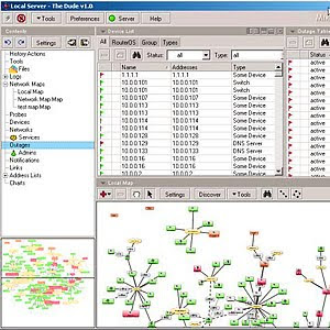
Membagi Bandwidth Tanpa Mikrotik
"Mas, bisa gak dengan peralatan kita yang sekarang untuk membagi Bandwidth untuk setiap klient?". itu kutipan pertanyaan yang sering dilontarkan baik di milis or di forum ini. Kemudian saya mencoba mencari referensi dar teman-teman yang sudah lebih dahulu terjun ke dunia internet tapi kebayanyakan dari mereka merekomendasikan menggunakan mikrotik. Wah selain harus beli saya pikir lebih baik saya mencari alternatif lain yang open source dan tentunya gatis ya saya salah seorang yg suka seusatu yang gratis, semoga anda juga demikian
berkat bantuan rekan saya Google.com akhirnya saya mendapatkan apa yang saya inginkan. ternyata sangat banyak tool yang dapat digunakan untuk membagi bandwidth dan penggunaannya sangat mudah sekali. Bahkan kalo anda menggunakan fedora core 5 anda tidak perlu susah-susah menginstallnya. Nah apa saja sih yang dapat digunakan? berikut adalah tool yang dapat digunakan:
Friday, 7 January 2011
RB250GS
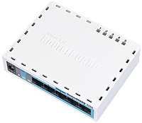
RB250GS
RB250GS is an Ethernet switch.
It has five Gigabit ethernet ports powered by an Atheros Switch Chip.
It is powered by a new operating system designed specifically for MikroTik Switch products - SwOS.
SwOS is configurable from your web browser. It gives you all the basic functionality for a managed switch, plus more: Allows to manage port-to-portforwarding, apply MAC filter, configure VLANs, mirror traffic, apply bandwidth limitation and even adjust some MAC and IP header fields.
RouterOS
Subscribe to:
Comments (Atom)


